 WENZHOU WEITUO VALVE CO., LTD.
Fail-safe operation requirements: Does the process need to automatically take safety measures in the event of a fault.
Valve action type: ATC (Air-to-Close): The valve opens when there is no air source and closes when there is an air source. ATO (Air-to-Open): The valve closes when there is no air source and opens when there is an air source.
Definition of direct action and reverse action Direct action (positive action) control valve loop: The controller output is proportional to the measured value. That is, when the process value increases, the controller output also increases; conversely, when the process value decreases, the controller output decreases.
Reverse action (negative action) control valve loop: The controller output is inversely proportional to the measured value. That is, when the process value increases, the controller output decreases; conversely, when the process value decreases, the controller output increases.
Controller minimum output and fail-safe action The minimum output of the controller should be able to achieve the required fail-safe action to ensure that the system can automatically enter a safe state when a fault occurs.
Example: For example, there are two controllers in a distillation tower: the reflux controller is reverse acting, and its control valve is ATC - FO (air-to-air closed, fault open), which is used to ensure that the valve is open when the gas source is lost to prevent overpressure.
The net top controller is direct acting, and its control valve is ATO - FC (air-to-air closed, fault closed), which is used to ensure that the valve is closed when the gas source is lost to prevent material leakage.
Basic components of a control valve loop A typical control valve loop contains the following basic components: Control parameters: process parameters such as flow and pressure. Process controller: responsible for initiating the action of the control valve. Valve positioner: as the most basic and necessary component, used to accurately adjust the valve position. Control valve: performs the actual flow or pressure regulation.
Operation mode of control valve loop A control valve loop has two main operation modes: Direct-acting loop: the controller output increases as the process variable increases, which is suitable for situations where the output needs to be increased when the PV is higher than the set point.
Reverse-acting loop: the controller output decreases as the process variable increases, which is suitable for situations where the output needs to be reduced when the PV is higher than the set point.
Operating Mechanisms of Direct-Acting Control Valve LoopsController Action: As the process variable or parameter measurement increases, the controller output signal increases accordingly; conversely, as the process variable decreases, the controller output also decreases.
Valve Positioner Action: As the controller output signal increases, the air pressure or output load of the valve positioner also increases; conversely, as the controller output decreases, the air pressure or output load of the valve positioner also decreases.
Control Valve Action: When the load or air pressure on the valve actuator increases, the valve plug moves toward the closed position for ATC-FO type valves and toward the open position for ATO-FC type valves.
Operating Mechanisms of Reverse-Acting Control Valve LoopsController Action: When the process variable or parameter measurement increases, the controller output signal decreases proportionally; conversely, when the process variable decreases, the controller output increases.
Valve Positioner Action: When the controller output signal increases, the air pressure or output load of the valve positioner decreases accordingly; conversely, when the controller output decreases, the air pressure or output load of the valve positioner increases.
Control Valve Action: When the load or air pressure on the valve actuator increases, the valve plug moves toward the closed position for ATO-FC type valves and toward the open position for ATC-FO type valves.
Application ExampleConsider the case where a flow control valve is installed at the process input, an ATC control valve is used to regulate the flow, and the tank level is the process variable. If the tank level rises above the set point, the controller output must increase to close the valve in order to correct the error, so in this case, the controller should select direct action. In contrast, if the flow control valve used is an ATO instead of an ATC, the controller should select reverse action.
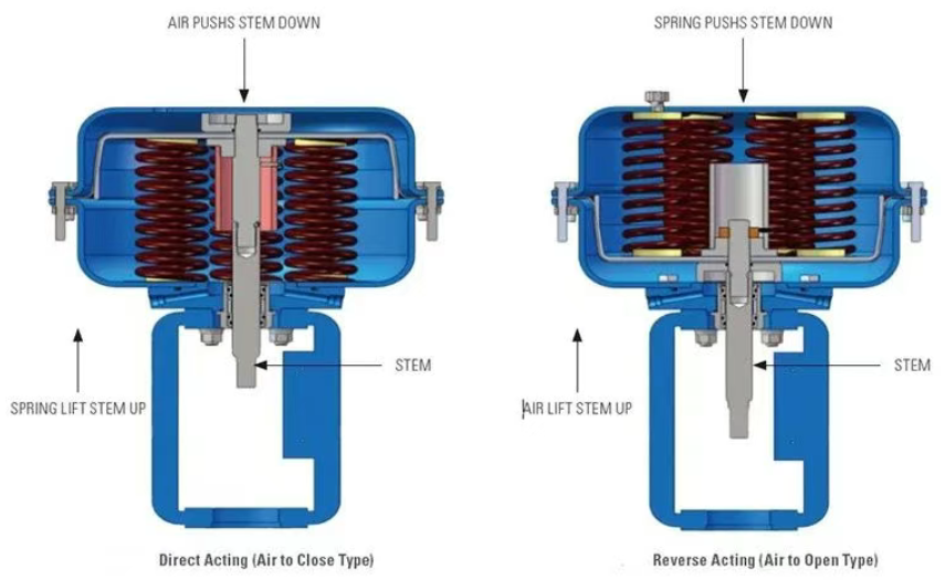
Direct-acting push-stem valve: When the applied pneumatic pressure increases, the valve stem is pushed down, causing the valve to close.
Reverse-acting push-stem valve: When the applied pneumatic pressure increases, the valve stem is lifted, causing the valve to open.
Fail-safe mode The fail-safe mode of a pneumatic valve or spring-actuated valve depends on the design of the actuator and valve body. For example, a pneumatic valve may be designed to automatically open or close when the air supply is lost to ensure the safety of the system.
The choice of controller action and its impact on the entire control system. Correctly configuring the controller action not only helps optimize the process flow, but also improves the reliability and safety of the system.