 WENZHOU WEITUO VALVE CO., LTD.
This article will introduce three types of pressure relief valves in three parts. In the first article, we will introduce the basic operation of spring-loaded safety relief valves. In future articles, our second article will introduce the operation of pilot-operated safety valves, and the third article will introduce the operation of safety valves.
Pressure relief valve (PRV) is a term used to describe a class of valves designed for overpressure protection applications. You may have heard of many different PRV terms: safety valve (SV), relief valve (RV), safety relief valve (SRV), or pilot-operated safety relief valve (POSRV).
Pressure relief valve (PRV) A device designed to open and release excess pressure, closing and preventing the flow of fluid after normal conditions are restored.
Relief valve (RV) A spring-loaded pressure relief valve actuated by the static pressure upstream of the valve. Relief valves are mainly used for incompressible fluids. Safety Relief Valve (SRV) - A spring-loaded pressure relief valve that can be used as a safety valve or a relief valve depending on the application.
Pilot-operated Safety Relief Valve (POSRV) A pressure relief valve in which the primary relief device or main valve is combined with and controlled by a self-operated auxiliary relief valve called a pilot valve.
Safety Valve (SV) A spring-loaded pressure relief valve actuated by static pressure upstream of the valve and characterized by a quick opening or pop-up action. Safety valves are typically used for compressible fluids, primarily steam.
Spring-Loaded Safety Relief Valve (SRV)
Now, let’s get into the subject of this article, the basic operation of a spring-loaded safety relief valve (SRV).
Spring-loaded safety relief valves are designed to protect pressure vessels or industrial systems from damage due to overpressure. Its basic construction includes the following core components:
Inlet nozzle
Directly connected to the vessel or system to be protected, ensuring that the media can flow smoothly into the valve.
Movable disc
Located above the nozzle, it can move up and down to control the flow of media through the nozzle. Under normal operating conditions, the disc is in a closed state, blocking the flow of fluid; when the system pressure exceeds the set value, the disc is pushed up, allowing the excess pressure or fluid to be released.
Spring mechanism
Responsible for maintaining the closed state of the disc and providing the necessary opening force when the pressure rises abnormally. The preload of the spring determines the valve’s opening pressure point, which is the threshold at which the safety valve activates and begins to discharge fluid.
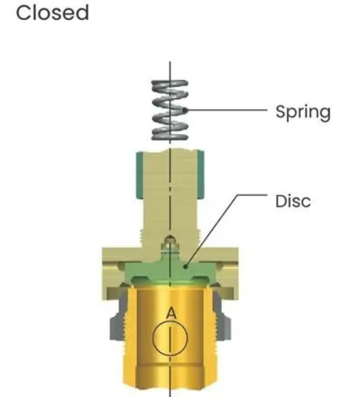
The working principle of the valve is to use the inlet system pressure to overcome the spring load, thereby opening the valve to release the specified capacity. When the valve is closed, as shown in Figure 1, the spring force counteracts the upstream pressure acting on the valve seat surface (area A). As the pressure increases, the pressure at (A) tends to be equal to the spring force, the valve disc returns to the valve seat, and the pressure approaches zero.
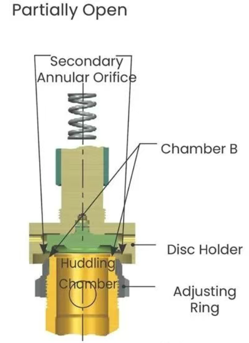
As shown in Figure 2, when the upstream pressure increases to within 1% to 2% of the valve set pressure, the medium will pass through the disc surface into chamber B. The flow restriction in the secondary annular orifice causes the pressure to increase and act on a larger area, creating additional force to overcome the spring force. The disc will then leave the nozzle seat and the valve will "pop" open.
After the valve opens, additional pressure buildup occurs at (C), as shown in Figure 3. This is due to the sudden increase in flow and the restriction of flow through another annular orifice formed between the inner edge of the disc holder and the outer diameter of the adjusting ring. These additional forces at (C) cause the valve plug to rise significantly as it "pops out". Flow is restricted by the opening between the nozzle seat and the valve seat until the valve seat is lifted off the nozzle seat by approximately one-quarter of the nozzle throat diameter.
After the disc has reached this level of lift, flow is restricted by the main orifice rather than the area between the seat surfaces. Venting (the difference between opening and closing pressures) can be controlled within a certain range by positioning a single adjusting ring. Venting occurs when the spring force is unable to overcome the sum of the forces at (A), (B), and (C) until the pressure at (A) drops below the set pressure.
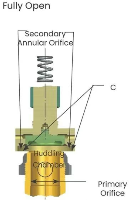
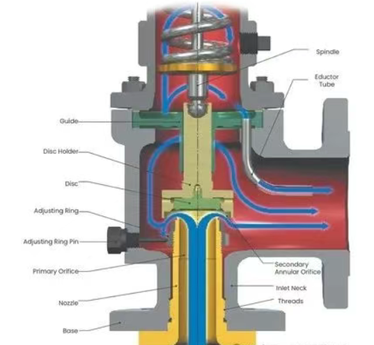
Figure 4 below is a schematic diagram of fluid flow through the valve. Note that the system pressure enters the nozzle and remains at high pressure until it expands through the secondary annular orifice. The pressure downstream of the secondary annular orifice is much lower than the system pressure.
Adjusting Ring
The adjusting ring in a safety relief valve is set to a predetermined position before the valve is placed in service. Presetting eliminates the need to open the valve when it is placed in service to determine if the adjusting ring is set correctly to achieve the necessary lift and relief capacity.
Simple Exhaust AdjustmentA single adjusting ring adjusts the exhaust or backfill pressure in a safety relief valve. When the adjusting ring moves up, exhaust volume increases (lowers restart pressure); when the adjusting ring moves down, exhaust volume decreases (raises restart pressure). In contrast, when a valve has two or more adjusting rings, each adjusting ring affects the valve's action as well as exhaust.
Common Industries and ApplicationsSpring-loaded SRVs are used in a wide range of industries. Some common industries include power generation, refining, petrochemical, chemical, midstream oil and gas, upstream oil and gas, and pulp and paper. Some common applications for spring-loaded SRVs include distillation, hydroprocessing, reforming, cracking, blending, fractionation, charge gas compression, separation, compression, pipeline integrity, dehydration, and balance of plant applications for gas, liquid, and two-phase applications.
The operating principle of a spring-loaded SRV is very simple, with only a few elements that control its function. There is much more to discuss about SRVs, such as the types of trims, how they are operated, and when to use a specific trim, but for now we will just discuss the basic principles of SRV operation. Stay tuned for the next two articles on pilot operated safety relief valves and safety valve operation.