 WENZHOU WEITUO VALVE CO., LTD.
A safety valve (SV) is a spring-loaded pressure relief device that is driven by the static pressure of the upstream medium and has the characteristic of opening quickly or "tripping". This type of valve is mainly used for compressible fluids, especially steam systems. According to the certification standards, safety valves can effectively protect equipment from damage under overpressure conditions not exceeding 3% of the system maximum allowable working pressure (MAWP).
The design of safety valves usually exposes the spring to facilitate inspection and maintenance without disassembling the valve. There are two main constructions: one is a sturdy column design (Figure 1), which is suitable for high-pressure and high-temperature conditions; the other is a multi-purpose bracket design (Figure 2), which is suitable for low-pressure and low-temperature applications.
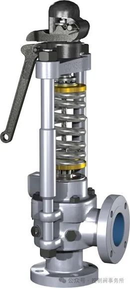
Figure 1: Side rod construction.
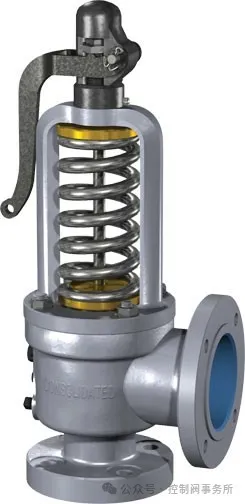
Figure 2: Yoke design.
Operational basis of safety valve
As shown in Figure 3, when the working pressure at the safety valve inlet is lower than the downward force of the spring, the valve remains closed. To ensure the tightness of the valve seat, the working pressure should be maintained at or below 95% of the set pressure.
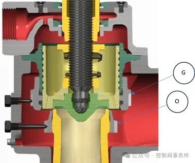
Figure 3: Safety valve in closed position.
When the working pressure reaches the critical point, as shown in Figure 4, steam begins to overflow from the valve seat surface into the valve cavity. In the gap formed between the upper adjusting ring (G) and the lower adjusting ring (O), the local restriction of the fluid causes the pressure to increase, acting on a larger area, generating an additional force sufficient to overcome the spring force. At this time, the valve core is separated from the valve seat, and the safety valve "trips" at the set pressure.
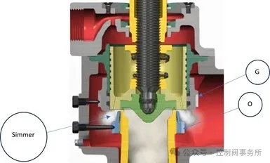
Figure 4: Safety valve “simmer point.”
Once the safety valve is opened, the position of the upper adjusting ring (G) directs the steam to change direction, increasing the lifting force and causing the valve core to reach full stroke. If the positions of the upper adjusting ring (G) and the lower adjusting ring (O) are adjusted properly, full stroke opening can be achieved (Figure 5). When the full stroke is reached, the limit stop (M) contacts the cover plate (P), eliminating vibration and enhancing valve stability. Steam enters the valve chamber (H) through the exhaust hole (J) on the adjusting ring, and at the same time, the main shaft ring (K) rises to a fixed position above the floating seal (L). Due to the difference in the two diameters of the overlapping rings, the working area between the floating seal and the main shaft is enlarged. The steam (H) enters the chamber (Q) through the secondary gap formed by the main shaft and the floating seal (L) and the ring (K), and is then released to the atmosphere through the exhaust port (N) and through the pipe discharge interface (R). Additional steam flows through the gap between the floating seal (L) and the ring (K).
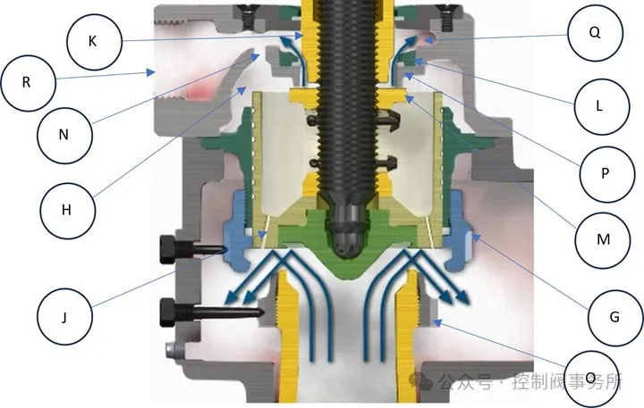
Figure 5: Safety valve at full lift position.
During closing, as shown in Figure 6, the spindle collar (K) descends into the floating seal (L), effectively reducing the amount of steam discharged from the valve chamber (H). The instantaneous pressure buildup in the chamber (H), at a rate controlled by the exhaust port (N), generates a downward spring loading force. The combined force of pressure and spring force ensures rapid and accurate closing of the valve. The residual steam pressure above the disc holder assists the spring in returning the disc to the seat. The cushioning during closing is controlled by the lower adjusting ring (O).
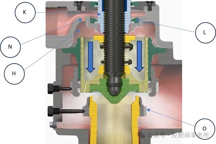
Figure 6: Safety valve closing.
Safety valve features
Column structure
The column is located outside the safety valve body to avoid direct contact with the boiler's high temperature and maintain a relatively stable temperature. The double columns allow the valve body to expand and contract with the boiler without affecting the performance of the safety valve, ensuring the stability and predictability of the set pressure.
Thermosensitive disc
Thermosensitive disc (P) is placed on the valve seat to form the sealing surface of the safety valve. It is usually made of chromium-nickel-inconel alloy, which has excellent corrosion resistance and can maintain the valve seat sealing even under high temperature and high pressure conditions. The thin and flexible edge design allows the disc temperature to quickly synchronize with the steam temperature, reducing deformation caused by steam throttling to the atmosphere. This design helps pressure-assisted mechanical closure and improves the valve seat sealing. The thermosensitive disc provides a low-friction fulcrum for the spring force, evenly distributes the force on the valve seat area, prevents tilting, maintains concentricity with the bushing, ensures reset accuracy, and avoids misalignment damage.
Cover assembly
The cover (P) quickly discharges steam to ensure full stroke opening. During the discharge process, the cover guides the steam to a safe direction, isolates the spring from the high-temperature steam, and reduces spring fatigue.
Overlap rings
Adjusting the upper adjustment ring (G) and the lower adjustment ring (O) optimizes discharge for short preheat and clean burst. Proper fine-tuning of the overlap ring (K) can achieve 3% discharge efficiency with pressure assistance.
Common industries and applications
Safety valves are widely used in the power industry, but also serve the refining/petrochemical, chemical, paper, metal processing, mining, and textile industries that use boilers to produce steam. Typical application scenarios include boilers, superheaters, reheaters, economizers, feedwater heaters, etc.
In summary, we have deeply analyzed the basics of pressure relief valves and recognized the uniqueness of spring-loaded safety valves, pilot-operated safety valves, and safety valves in operation and application. These devices are the last line of defense against explosions, fires, and accidental releases, and are critical to ensuring the safety of personnel and property.